Members Articles
HOME BREWED FOOT SWITCH
By Gavin Tse, DV1UST
August 2019
Objective
To be able to design a foot switch that functions as an alternative or secondary PTT (push to talk) button that keys the microphone and modulate the carrier frequency.
Limitation
This discussion about foot switch is not capable of dual triggering, which is typically used in conjunction with a power amplifier that needs to be keyed prior or in conjunction to the radio transmitting. Furthermore this is not a “plug and play” type of foot switch since it will still utilize an interface cable from the radio the microphone and the PTT. Though the home brewed foot switch tends to be almost universal to all interface cables, please do ensure proper pin outs of your interface cable, microphone and transceiver compatibility.
Materials Needed
- Hand Tools
- A typical basic hand tools will do which composed of a set of screw drivers, pliers, wire stripper/ wire cutter.
- Soldering Iron
- Any wattage will do.
- De-soldering pump
- This is optional.
- Soldering Lead
- A rosin core type is typically used.
- Multi-meter (Tester)
- Either an analog or digital multi-meter will do since we are only to use this to check for continuity.
- Mono Plug
- This will depend on the interface cable you currently have but I will be using a 6.35mm for my demonstration.
- Wire (at least a pair)
- The wire typically comes in pair if you decide to use an independently twined one you would be needing two of them. The gauge should not matter much neither does a solid or a stranded one will do as long as it will mechanically hold both the jack and the footswitch hanging on either ends when soldered. The length of the wire will also depend on your set up.
- Some might and will be using additional wires for chassis ground or a shielded wire, this shouldn’t be an issue as long at least a pair is needed for closing the circuit.
- Foot switch
- They do come in a set which typically consist of the chassis of the foot switch, inside containing a spring to actuate the micro-switch when pressed and a very short useless wire dangling outside.
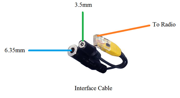
Radio interface cable
- This will depend on the transceiver you are using, different brand and different models have different pin out configuration and is not covered in this discussion so please do check and verify first that it is working and compatible since if plugging in our home brewed footswitch may cause damage to the equipment if not properly configured.
- Be careful on the microphones you would be using in conjunction with the interface cable, though this is not covered and discussed in this article please ensure that the interface cable you purchase or home brewed is compatible for the microphone you are to use with your radios.
Assumptions
The user is knowledgeable in using a multi-meter
The user is capable of using a soldering iron and basic hand tools
It is assumed that the user will utilize its best judgment on safety procedures
It is assumed that the user has a compatible and working interface cable
Discussion
There are a lot of foot switch in the market that is tailored fit to your preference and need available in the form of a “plug and play” concept. Some may and does cost a fortune to own one, but if you are a casual user which is eyeing to create one for personal use, this article may be of help to you.
There are foot switch or treadle switch as some stores name them are available in different electronic stores around Gonzalo Puyat Street (formerly Raon), they do also come in different sizes and some are of industrial grade and type, you may also opt the foot switch that were designed to be used in musical instruments but I find them pricey for the intended purpose.
Steps:
- Disassemble the foot switch and the Mono Plug
- Peel off a part of the insulation of the wire on both ends exposing the conductor within
- De-solder or disconnect the short dangling wires connected in the micro-switch
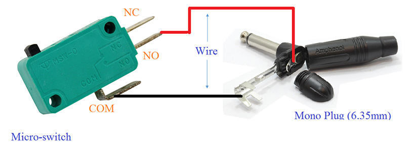
- Connect the desired length of wire to the one to the common and the other to the normally open terminal indicated as COM and NO in the micro-switch respectively, leaving the normally closed (NC) terminal hanging. Please read labels carefully.
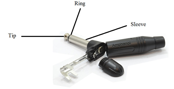
- Solder the other end of the wire to the Mono Plug one on the connection to the tip and the other to the sleeve and not on the plug itself.
- Check for continuity using the multi-meter
a. Check the working status of the micro switch for they are prone to internal shorts due to moisture
b. The wires could be interchanged since it only functions as a connection of a switch, as long as they are not shorted and each of which corresponds to only one of the other end when the switch is de-pressed.
c. When the switch is pressed the tip and the sleeve of the Mono plug must indicate a shorted connection otherwise open
- Reassemble the parts of the foot switch and the Mono Plug double checking each connection and assessing the well placement of its components.
- Watch out for cold solder!
- The connections must be able to mechanically support themselves on their intended load
- Verify if it’s working.
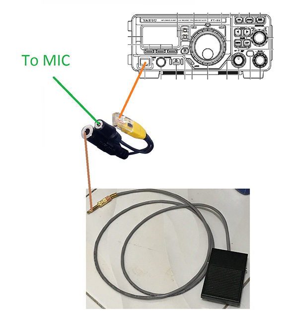
Typical Set-up
All images are copyright of their respective owners.