The design and construction of a “dual band-dual dipole” antenna is to build a dual bander HF antenna to be used on 21mhz and 28/29mhz amateur band. The design incorporates the simple dipole antenna with a direct feed line on the center of the two dipole. The SWR reading of the antenna is 1.3 with the use of antenna tuner, the readout can be improved to 1:1. The antenna can be packed and unpacked easily for field operation and may be used in pursuing DX contacts. The only setback is the need for a bigger diameter aluminum elements and a rigid holder to withstand high wind pressure. The elements and parts of the antenna are available locally and is shown below.
The dimension of the antenna are as follows; the dipole for 21MHz, using center frequency of 21.200MHz and formula of 468/frequency in MHz, 468/21.200 = 22.075 feet. Converting the value to meters, 22.075 meters is equal to 6.73m for the whole length of the dipole. Using the half width, one (1) side of the dipole is 3.365m. The computation hereunder is for a dipole using #16 AWG copper wire used as electrical house wire.
Since the project is to use an aluminum tubing, the lengths were varied to make the antenna work fine. For the 28/29MHz bandwidth, using center frequency of 28.7MHz, the dimension should be 468/28.7 = 16.30’ or 4.97 meters for entire length and 2.4857m on its half width. The spacing of the element should be a minimum length of 20cm for the antenna to radiate effectively.
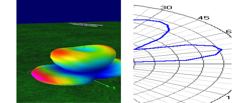
To get the correct and nearest values for the behavior of the antenna, we use the 4NEC2 software developed by Arie Voors. The model in three dimensional which is the result of the pattern radiation of the antenna.
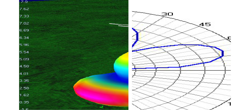
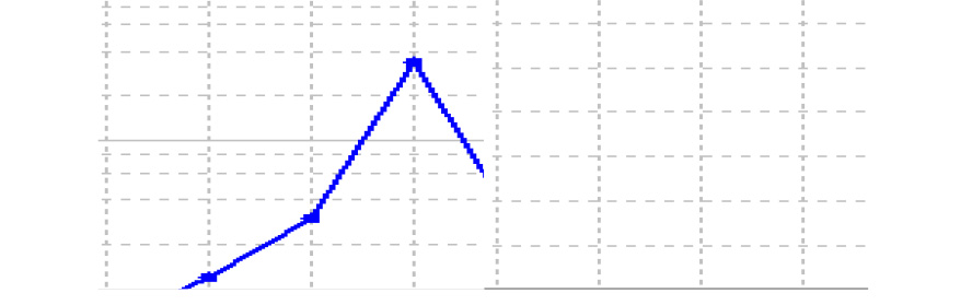
SWR results from sweeping into 20MHz – 30MHz frequency, the antenna performs very well on the desired frequency.
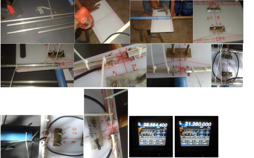
Materials
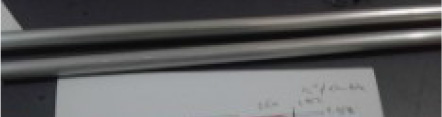
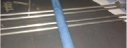
Elements: aluminum tubing ½” and 3/8” diameter. Cut into length for the dipole.
Holder: Holder: Chopping board ½” thick and can hold the elements, sturdy even in high winds. Chopping board is cheap compared to ¼” thick PVC materials./p>
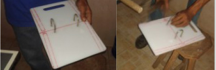
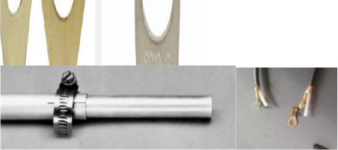
Connectors: Steel hose clamp 1” in diameter to hold the elements and also used for the element to element connection at tapered locations. Eye terminal was also used for connection of the coaxial cable to the elements.
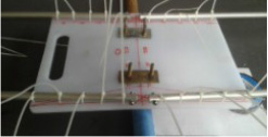
The boom is made up of ¾ PVC pipe reinforced with round wood inserted into the PVC tube.
Plastic ties of assorted sizes were used to fasten the elements into the holder and fishing nylon string were used to support the elements to the center wooden post attached to the PVC tubing.
Assembly
Installation of the antenna on rotator
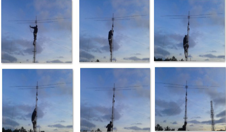
The antenna was tested and used during the American Radio Relay League 10m Contest held last December 10-11, 2016 and I managed to take 3rd place-DX on QRP.
